

Hydraulic Decoking Systems
Overview
Conventional Delayed Coking is a useful and economical refinery process to convert fractions of crude oils. Today due to many improvements in coking and decoking techniques and product demands Delayed Cokers are often built to make coke. The fresh coker feed is pumped into the fractionation tower and the conditioned coker feed being pumped out from the bottom to the furnace. Furnace effluent is feeded into the drum with the overhead vapours returning to the fractionation tower.
Delayed Coking is a process which produces gas, gas oils and coke. The furnace provides the heat which starts the vaporisation and cracking at approximately 485° C (905° F). As the feed enters the drum at the bottom the cracking and polymerisation continues until solid coke is formed and the gases go overhead to the fractionation tower. When the drum is nearly full the feed is switched over to the second drum. The various types of coke produced are fuel coke, sponge coke, needle coke and shot coke.

Design Features
System calculated, designed and
manufactured for the
demands of the customer
Ambient conditions:
Ortam koşulları -45 °C (-49 °F) ila +50 °C (+122 °F) arasında değişebilir
Ambient conditions:
Normal water; seawater.
Area Classification:
According to standard of refinery.
Hoist:
Hydraulically (preferred), electrically or pneumatically driven hydraulic power unit for hoist and Drill Stem Drive.
Drive Unit:
Crosshead, running in 4 points. Heavy load wheels, Free Fall Arrestor for high safety. Gearbox for heavy-duty service with grease lubricated axial bearing for high load.
Tools:
Combination Drilling and Cutting Tool.
Control System:
PLC-System for Process Data Measurement. Data Logging and Visualisation. Automatic Interlocking System.
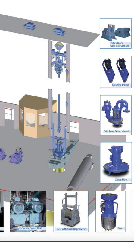
- Hoist – Hydraulically or electrically driven
- HPU – Hydraulic Power Unit (in case of hydraulically driven hoists and/or Drill Stem Drive and/or Deheading System container version) – not shown
- HPW – High Pressure Water line, flexible hose or swing pipe
- LCP – Local (Operator) Control Panel free-standing or installed in operator shelter (optional) one panel for one pair of drums.
- CH + FFA – Crosshead with Free Fall Arrestor
- DSD – Drill Stem Drive, hydraulically or electrically driven
- PB – Single and double Pulley Block equipped with instruments for rope load and tool position
- Guide Rails – T-type guide rails with shims, connectors, bolts and nuts with latching mechanism and proximitor switches
- DS + Tool – Drill Stem (threaded or welded), Tool (manual or autoswitch tool)
- TOP-Unheading Device – Automated Top Unheading (optional) Device, electrically or hydraulically driven
- Feed Entry – (optional) side entry connection of feedline, separate or connected to cone
- Bottom Unheading Device – (optional) automatic bottom unheading system hydraulically driven, with hanger and installation system
- LCP – Local (Operator) Control Panel for bottom unheading system, installed in an operator shelter (optional), for close and remote operation - not shown

Pump Unit and Main Control Panel
- Pump Unit – Pump – (Gear) – Motor unit
- LOS – Lube Oil System for Motor – (Gear) –Pump
- DCV – Decoking Control Valve
- MCP – Main Control Panel equipped with PLC, monitoring system and operation switches, push buttons and lamps
Cuttingdeck with details
Crosshead with Drill Stem Drive
Crosshead Design
Standard components of heavy-duty industry
■Guide rails
■Wheels
■Free Fall Arrestor
■Double block
Functional test
■ Simulation of broken rope
Drill Stem Drive
Standard components of heavy-duty industry
■Main gear, grease lubricated
■Auxiliarygear,oillubricated
■Packingcartridge
■Drivewithhydraulic,electricorpneumatic motor
High torque at the Drill Stem
■ Highgearratio
■ Main gear without sealing at the Drill Stem
Control Tool Position
■ Measurement of torque and speed at the Drill Stem
■ Manualoverrideformax.torque (optional for hydraulic systems)
Favourable maintenance
■ Cartridgesystem

| Test Condition of Drill Stem Drive | |
|---|---|
| Hydro test | 525 bar (7,800 psi) |
| Functional test | 15 rpm at 350 bar (5,200 psi) |
| Measurement | Torque leakage |
| Hoist, Hydraulically Driven | |
|---|---|
| Pull force | 45 kN (9,900 lbsf) |
| 4,500 kg (9,912 lbsf) | |
| Compact Design | |
| Low noise | |
| Pull speed (hoist) | up to 70 m/min (230 ft/min) |
Combination Cutting Tool
Basic design
- Slim tool, diameter 13" (310 mm)
- Lowliftforce
- Low torque
- Hydrodynamic optimised channels
Switching device
- Manual/automaticswitch
- Atthetopofthetool
Valves
- Ballshapevalves
- No seals
- Pressureoperated
Guide Plate
Basic Design
- CenteringDevice
- SafetyLatches
Dome
- with Vent /Chimney
- DrillStemGuide
Top Deheading
Automatic
- Doublegate/slidevalve (by others)
- Electrically (preferred) or hydraulically driven
- Adapter to guide plate
- OperationviaRuhrpumpen control system
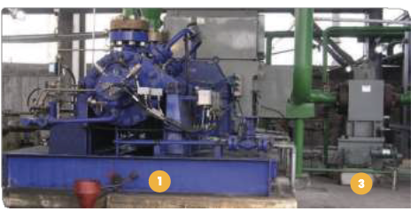
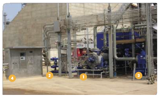
Centrifugal Process Pumps in Barrel Type Design

ADC barrel pump for Hydraulic Decoking service
The ADC pump can pump fluids up to 400 m3/h (1,760 gpm) and a head of 4000 m (13120 ft). These pumps are mainly used as water injection pumps and jet pumps for hydraulic decoking in refineries. The pumps are of significantly robust and heavy- duty construction. They are built according to API 610 last edition, with special modifications available for individual working conditions. The pump is mostly direct driven by a motor; higher speeds are achievable through a drive by a gear box or a steam turbine. Lube Oil System according to API 610 and/or 614 is included in the system as a standard component.
Bearings
Forced-feed oil lubricated axial and radial bearings as sleeve bearings, oil supply by lube oil pump driven by the pump shaft and/or separate lube oil unit.
Standard materials
Casing -forged carbon or alloy steel
Impeller -cast steel, alloy steel
Pump shaft -alloy steel
Application
High pressure cutting water
| Performance Range | ||
|---|---|---|
| Capacity | up to 400 m3/h | up to 1760 gpm |
| Head | up to 4000 m | up to 13120 ft |
| Temperature | up to 150°C | up to 302°F |
| Speed | High speeds available on request. | |

Cutting System Components
Freefall Arrestor
Ruhrpumpen has developed freefall arrestor retrofit designs which can most times be installed without interruption to your decoking operations.
Features
Operational testingeasily performed on a routine basis Arrestor cables and cable guides eliminated Cablegrippersareeliminated TÜV (UL/FM equivalent) approved with over 5,000 installationsDrill Stem Drive
Our drill stem drive (DSD) can normally be installed without interruption to decoking operations. The DSD fits within the existing swivel envelope (+/– 3”) and can be adapted to existing crossheads without modification to the control limit switches or mechanical stops. Additionally, should time permit, the connection to the drill stem can be revised from a unibolt coupling to a flanged connection or FlangeLok or equal connection.
Coke Cutting Tool
Ruhrpumpen’s patented design combines a drilling and cutting tool.
Basic design
Slimtool,diameter13”(310mm) Lowliftforce Low torque Hydrodynamic optimised channelsSwitching device
Manual/AutomaticswitchAtthetopofthetoolNozzles, Cutting
0°10° upbothperipherynozzles